
You are here: Home1 / Blog2 / Product Knowledge3 / How to Size Industrial Hoses: Flow Rate & Diameter Guide
How to Size Industrial Hoses for Required Flow Rate
1. Understand the Relationship Between Flow Rate and Hose Size
Flow rate refers to the volume of fluid passing through a hose within a specific period. It is commonly measured in:
- L/min (liters per minute)
- m³/h (cubic meters per hour)
- GPM (gallons per minute)
- CFM (cubic feet per minute, commonly used for air)
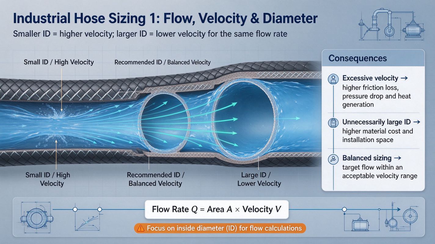
Hose diameter directly affects fluid velocity. For the same flow rate, a smaller hose diameter produces higher fluid velocity, while a larger diameter reduces velocity.
If the hose is too small, excessive velocity can increase friction losses, pressure drop, and heat generation. If it is unnecessarily large, material costs and installation space may increase.
Therefore, the goal is to select a hose diameter that delivers the required flow rate within an acceptable velocity range.
2. Calculate the Required Hose Inside Diameter
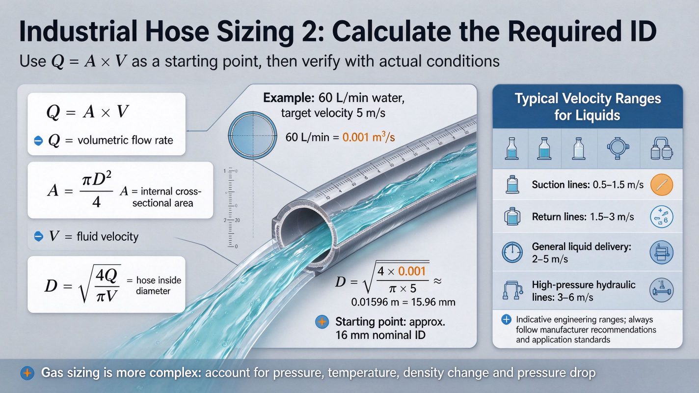
The basic relationship between flow rate, velocity, and hose cross-sectional area is:
Q = A × V
Where:
- Q = Volumetric flow rate (m³/s)
- A = Internal cross-sectional area (m²)
- V = Fluid velocity (m/s)
Since the hose has a circular cross-section:
A = π × D² / 4
Combining these equations gives the formula for calculating the required inside diameter:
D = √(4Q / πV)
Where D represents the hose inside diameter.
For example, suppose an industrial water transfer system requires a flow rate of 60 L/min, with a target fluid velocity of 5 m/s.
First, convert the flow rate:
60 L/min = 0.001 m³/s
Then calculate the required diameter:
D = √(4 × 0.001 / (π × 5))
D ≈ 0.01596 m = 15.96 mm
Therefore, a hose with a nominal inside diameter of approximately 16 mm would be a reasonable starting point.
This calculation provides a preliminary size. The final selection should also consider actual hose dimensions, pressure loss, fittings, and operating conditions.
3. Choose the Appropriate Fluid Velocity
Different applications require different flow velocity ranges. The recommended velocity depends on the type of medium, hose construction, pressure conditions, and system design.
For liquid transfer applications, the following values can serve as preliminary reference ranges:
| Application | Typical Velocity Range |
| Suction lines | 0.5–1.5 m/s |
| Return lines | 1.5–3 m/s |
| General liquid delivery | 2–5 m/s |
| High-pressure hydraulic lines | 3–6 m/s |
These are indicative engineering ranges, not universal limits. Always follow the hose manufacturer’s recommendations and applicable application standards.
For example, suction hoses generally require lower fluid velocity to reduce pressure losses and minimize the risk of cavitation or hose collapse.
For compressed air and other gases, sizing is more complicated because gas density changes with pressure and temperature. Engineers must consider actual volumetric flow, operating pressure, temperature, and pressure drop rather than applying liquid velocity guidelines directly.
4. Consider the Type of Industrial Hose
Different hose materials and constructions serve different applications. Selecting the correct diameter is only one part of the process.
PVC Hoses: Commonly used for water delivery, agricultural irrigation, air transfer, and general industrial applications. Their flexibility and cost-effectiveness make them suitable for many general-purpose systems.
PU Hoses: Often selected for dust collection, pneumatic conveying, and abrasive material handling. Their abrasion resistance makes them useful where particles move through the hose.
Rubber Hoses: Widely used for water, oil, air, chemical, and other industrial fluid transfer applications. The rubber compound and reinforcement must match the conveyed medium and operating conditions.
Silicone Hoses: Used in applications requiring temperature resistance and flexibility, subject to the specific silicone compound and construction.
Utigoflex offers different industrial hose solutions for various fluid and material transfer requirements. The appropriate hose type should always be selected according to the application and operating environment.
5. Check Working Pressure and Pressure Drop
After calculating the required inside diameter, verify that the selected hose can withstand the system’s working pressure.
A hose with a suitable diameter may still be unsuitable if its pressure rating is insufficient.
Consider the following factors:
- Maximum continuous working pressure
- Pressure surges during operation
- Hose reinforcement structure
- Temperature-related pressure limitations
- Fitting and connection pressure ratings
Pressure drop is another important consideration. It occurs as fluid moves through the hose due to friction and flow resistance.
A smaller diameter generally produces greater pressure loss at the same flow rate. Long hose lengths, bends, fittings, and valves can further increase resistance.
For critical systems, pressure drop should be calculated using an appropriate engineering method rather than relying on diameter calculations alone.
6. Consider Hose Length, Bends, and Installation Conditions
The installation environment also affects hose selection and system performance.
Hose Length: Longer hoses generally create greater friction losses. If the required flow rate is high, a larger inside diameter may be necessary.
Bend Radius: Excessive bending can restrict the internal flow area and increase stress on the hose reinforcement. Always observe the manufacturer’s minimum bend radius.
Fittings: Reduced internal passages in fittings and connectors may create additional flow resistance, even when the hose diameter is correctly selected.
Ambient Conditions: Temperature, vibration, external abrasion, and exposure to chemicals can affect hose service life.
These factors should be evaluated before finalizing the hose specification.
7. A Practical Checklist for Industrial Hose Sizing
Before purchasing or specifying an industrial hose, confirm the following information:
- Required flow rate and measurement unit.
- Conveyed medium and its properties.
- Target fluid velocity.
- Required hose inside diameter.
- Maximum working pressure.
- Operating temperature range.
- Hose length and installation layout.
- Fitting dimensions and connection type.
- Chemical compatibility and environmental conditions.
At Utigoflex, understanding these operating requirements helps customers identify suitable hose products for different industrial applications.
Conclusion
Correct industrial hose sizing starts with understanding the relationship between flow rate, fluid velocity, and inside diameter. However, a reliable selection also requires checking working pressure, pressure drop, hose material, temperature, fittings, and installation conditions.
By evaluating these factors together, buyers and engineers can select hoses that meet system requirements while improving transfer efficiency and operational reliability.
Looking for suitable industrial hoses for your application?
[Contact Utigoflex Today] to discuss your flow rate, operating conditions, and hose specifications.
FAQ
Q1: Should I choose a larger hose if the required flow rate increases?
Generally, yes. A larger inside diameter helps maintain a reasonable fluid velocity and reduce pressure losses when flow rate increases.
Q2: Is hose diameter the same as hose outside diameter?
No. Flow rate calculations use the inside diameter (ID), because it determines the available flow area. Outside diameter (OD) is mainly relevant to installation and fitting compatibility.
Q3: Can I use the same sizing formula for water and compressed air?
The basic continuity relationship applies to both, but gas is compressible. Accurate gas hose sizing must account for pressure, temperature, density changes, and actual versus standard volumetric flow.

